Embedded programming with Arduino on the Raspberry Pi Pico
Introduction
About Embedded Programming
Application Programming
Embedded Programming
Embedded Programming on Arm
Build a smart device prototype
Program your smart device prototype
Learn about interrupts
Add the interrupt code
Refactor the application
Next Steps
Embedded programming with Arduino on the Raspberry Pi Pico
Arduino IDE
To program your device you will use the Arduino IDE. In addition to being a nice simple code editor, the Arduino IDE will also handle device communication for you, and will build a compatible binary executable for your device.
Follow the Arduino core for the Raspberry Pi Pico install guide to get the Arduino IDE and device packages installed on your computer and the Arduino embedded OS installed on your Raspberry Pi Pico.
Load the PIR sensor sketch
This Learning Path provides a complete sketch that you can upload onto your Raspberry Pi Pico. A step-by-step guide is provided below.
First, open the sketch in the Arduino IDE:
- Right click and select
Save Link Asto save the pir_sensor.ino sketch to your computer - In the Arduino IDE, go to
File -> Open - Find and select the
pir_sensor.inofile that you just downloaded to your computer and clickOpen
Code walk-through
You should review the code and learn about what it does.
Define which pins your components are connected to
The first few lines of the code define new variables that will store the number of the pins that are connected to your physical components:
// This is the pin that the motion sensor is connected to
int motionPin = 28;

// This is the pin that the buzzer is connected to
int buzzerPin = 19;

// This is the pin that connects to the build-in LED
int ledPin = 25;
The first variable, motionPin, holds the number for the data connection on your PIR sensor, which is connected to pin #28.
The second variable, buzzerPin, holds the number for the peizo electric buzzer’s input voltage pin, which is connected to pin #19
The last variable, ledPin, holds the pin number for the LED that is built into the Raspberry Pi Pico, which is pin #25
Define runtime variables
The next few lines define the variables that the program uses to store its internal state:
// This variable will hold the current value of the motion detection pin's charge
// LOW means no motion is detected, HIGH means motion is detected
int motionState = LOW;

// This variable will hold the read value on each iteration of the loop
int val = 0;

// This variable will keep track of how many times motion has been detected
int counter = 0;
The motionState variable holds the value from the motionPin between checks, so you know what the previous value was. The default value for this variable is LOW, which corresponds to no motion detected.
The val variable holds the current value from the motionPin after each check.
Finally, the counter variable holds the number of times motion was detected since the device was turned on.
Helper functions
To make the code easier to read and maintain there are a few helper functions called from the main code:
// Beep the buzzer twice in quick succession
void doBeep() {
      digitalWrite(buzzerPin, HIGH); // On for 0.1 seconds
      delay(100);
      digitalWrite(buzzerPin, LOW); // Off
      delay(100);
      digitalWrite(buzzerPin, HIGH); // On for 0.2 seconds
      delay(200);
      digitalWrite(buzzerPin, LOW); // Off
}

// Turn on the built-in LED
void ledOn() {
  digitalWrite(ledPin, HIGH);
}

// Turn off the built-in LED
void ledOff() {
  digitalWrite(ledPin, LOW);
}
The first is doBeep() which turns on and off power to the buzzer in a way that makes it play two short beeps.
The next two, ledOn() and ledOff(), set the LED pin’s voltage to either HIGH or LOW, respectively, turning it either on or off.
Note that these functions use the pin variables defined at the start of the sketch.
Setup
Now it’s time to get into the actual program.
The Arduino Core software expects your sketch to provide two functions, setup() and loop(). The first of these, setup(), is called once and only once when your device is powered on. This is where you put code to initialize your environment and hardware:
void setup() {
  // Here we tell the board whether a pin will be used for reading (INPUT) or writing (OUTPUT)

  // This lets us write text over the USB connection to the Arduino IDE
  Serial.begin(9600);

  // We will read values from the motion sensor
  pinMode(motionPin, INPUT);

  // We will write values to the buzzer
  pinMode(buzzerPin, OUTPUT);

  // We will write values to the built-in LED
  pinMode(ledPin, OUTPUT);
  // We default to having the LED on, indicating a ready state
  ledOn();

  Serial.println("Beginning motion detection");
}
First, initialize the Serial interface so that you can write output over the USB connection. Serial.begin(9600) turns on the device’s onboard serial interface with a baud rate of 9600 (which is low but more than enough for writing output messages).
Next, the sketch tells Arduino core how each of the pins will be used, either as INPUT for reading voltage or OUTPUT for setting voltage. The motion sensor is the only pin we will be getting input from, for the others we will be setting it.
Once setup is done, call the ledOn() helper function to turn on the board’s LED, indicating that it’s setup and ready to start detecting motion. Additionally, write a message to the USB serial connection with Serial.println() to indicate the setup is complete.
Loop
Once the setup() function finishes, the Arduino core software calls the loop() function and keeps on calling it over and over again, as fast as it can, which means many times per second. Not only is this unnecessary most of the time, it’ll also result in a much higher energy use which will drain the battery very quickly.
void loop() {
  // put your main code here, to run repeatedly:

  // Every iteration of the loop has a half-second delay, this reduces the processing load on the device
  delay(500);
To avoid unnecessary execution, there is a half-second delay into each call of the loop() function. The delay(ms) function pauses execution for the defined number of milliseconds (ms), and then execution continues.
Motion detected
Next, review the logic of the motion detector. The first thing to do is read the state of the motion detector. This is done with the digitalRead() function provided by Arduino core. If the value (val) read is a high voltage, that means the detector has registered motion.
  // In every iteration of the loop we start by checking the current value from the PIR sensor
  val = digitalRead(motionPin);

  // A HIGH value means the sensor is detecting motion, so we do our motion-handling
  if (val == HIGH) {
Note that because of the nature of the passive infrared sensor and the fact that the code is running twice per second, it’s possible that you will read a HIGH value multiple times for the same motion event. But you really only want to respond once per event.
So, in order to determine if this is a new motion event or not, you need to check the motionState variable that stores the detection value between calls to loop().
No previous motion
    // If we had previously been in a LOW state (no motion) then this is a new detection!
    if (motionState == LOW) {
      // First we write to the USB console that motion was detected
      Serial.println("Motion detected");
      // Next we turn the LED off, indicating that we're not longer in the waiting state
      ledOff();
      // Then we trigger the beep
      doBeep();
      // And increment our counter
      counter++;
      Serial.print("Counter is now at ");
      Serial.println(counter);
      // Finally we save the fact that we're in a motion detecting state
      motionState = HIGH;
If the value of motionState is LOW, it means there wasn’t any motion detected in the previous iteration of our loop, so this is a new motion event and it generates a response.
The first thing the code does is print a message to the USB output, using the same Serial.println() used in setup(), to indicate that a new motion event has happened.
Next, call the ledOff() and doBeep() helper functions for visual and audible indications of motion being detected. Also, increase the number in the counter variable and print the new value to the USB output.
Lastly, set motionState to HIGH, so that in the next iteration of loop() the motion event has been responded to.
Previous motion
If, however, motionState was not LOW, then the HIGH value from the sensor isn’t a new event, and there is therefore no need to respond to it:
    // If we had previously been in a HIGH state (motion detected) then we're seeing the same motion event we've already handled
    } else {
      // PIR sensors can retain a HIGH state for several seconds after motion has stopped
      // So we're adding in a 10 second cooling off period to let it return to a LOW state
      Serial.println("Waiting for sensor to cool-off");
      delay(5000);
    }
Instead, simply print a message to the USB output indicating it wait for the next event and add a further 5 second delay to the loop() so that the sensor has a chance to revert back to the no-motion state (this takes 3-5 seconds for these sensors).
No Motion Detected
If the sensor returns a LOW value, it means it’s not currently detecting motion. When this happens, only respond if the previous call to loop() was detecting motion, indicating a change in state:
  // A LOW value means the sensor isn't detecting motion, so we enter a waiting state
  } else {

    // If we had previously been in a HIGH state, that means the PIR sensor has stopped registing motion
    if (motionState == HIGH) {

      // We save the fact that we're not in a non-motion detecting state
      motionState = LOW;
      // Next we turn on the LED to indicate that we've entered the motion detecting state
      ledOn();
      // Finally we write to the USB console that we're ready to detect motion
      Serial.println("Ready for detection");
      Serial.println();
    }
  }
All that needs to be done is to set motionState back to LOW so that any future motion detection will trigger a response. Also turn the board’s LED back on to give a physical indication that it’s in a ready state.
Finally, write a message to the USB output indicating that the device is once again ready to detect a motion event.
Run your code
Now that you have a good understanding of the code, you should run it on your device. With your Raspberry Pi Pico board plugged in to your computer, and the
correct board and port selected in the Arduino IDE
, click the Upload button on the IDE to build and install it on your device.
If successful, you should see the LED on your board light up. If you wave your hand in front of the sensor, you should also hear a double beep and see the LED turn off for a few seconds.
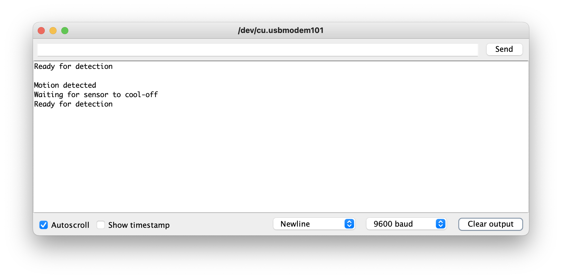
You can further check that your code is running properly by opening the Serial Monitor from the Tools menu of the Arduino IDE. There you should see all of the output messages, including count of detected motion events, coming from your sketch.
Congratulations! You have successfully programmed your microcontroller and built a working, if simple, smart device.
Continue on to see how to improve the application by replacing the loop() and delay() calls with interrupts.