The Xilinx Vivado tools provide a simplified way to create an AXI4 peripheral. You can follow the steps outlined below to create the peripheral.
Start by clicking “Tools” -> “Create and Package New IP”. Click “Next” and choose the following option:
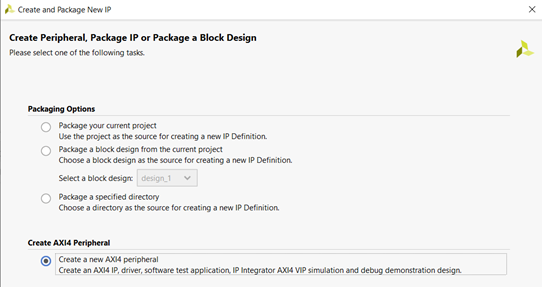
Figure 2.1. Creating AXI4 peripheral
Give the following name to the IP (you may keep the IP location path as provided by default):
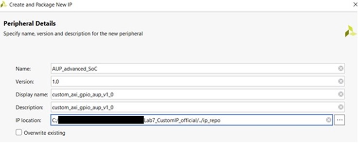
Figure 2.2. Adding peripheral details
You need a Subordinate interface and four 32-bit registers for the switches and LEDs.
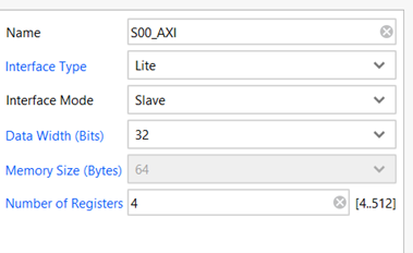
Figure 2.3. Peripheral settings for Subordinate interface
On the last page, choose “Edit IP” and click “Finish”. In the “Sources” window, you will see two Verilog files in Design Sources:
- A top file, i.e., AUP_advanced_SoC_v1_0.v
- A filename that ends with “S00_AXI”, i.e., AUP_advanced_SoC_v1_0_S00_AXI.v
These are the basic template files generated for an AXI-Lite peripheral. You can now implement custom GPIO logic by making some changes to these template files.
Double-click to open the top-level Verilog file called “AUP_advanced_SoC_v1_0.v”:
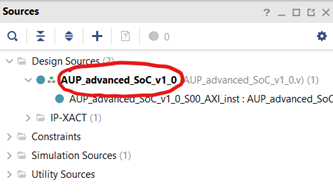
Figure 2.4. Editing top-level Verilog file
Add the following lines of code below the comment “// Users to add ports here”:
// Users to add ports here
input wire [3:0] sw,
output wire [3:0] led,
Also add sw and led when instantiating the AXI Bus Interface S00_AXI, so the code looks like the following:
// Instantiation of Axi Bus Interface S00_AXI
    AUP_advanced_SoC_v1_0_S00_AXI # (
        .C_S_AXI_DATA_WIDTH(C_S00_AXI_DATA_WIDTH),
        .C_S_AXI_ADDR_WIDTH(C_S00_AXI_ADDR_WIDTH)
    ) AUP_advanced_SoC_v1_0_S00_AXI_inst (
            .sw(sw),
            .led(led),
        .S_AXI_ACLK(s00_axi_aclk),
...
...
Save the changes in the file (Ctrl+S). Next, expand and open the other Verilog file (AUP_advanced_SoC_v1_0_S00_AXI.v) shown below:
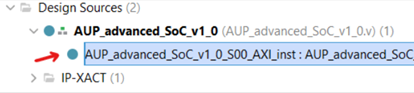
Figure 2.5. Edit the second Verilog file
Add the following lines of code below the comment “// Users to add ports here”:
// Users to add ports here
input wire [3:0] sw,
output wire [3:0] led,
Scroll down the file and search (Ctrl+F) for “// Address decoding for reading registers”. Then update the code so that it looks like the following:
// Address decoding for reading registers
case ( axi_araddr[ADDR_LSB+OPT_MEM_ADDR_BITS:ADDR_LSB] )
2'h0   : reg_data_out <= {slv_reg0[C_S_AXI_DATA_WIDTH-1:4], sw[3:0]};
Scroll down the file and search (Ctrl+F) for “// Add user logic here”. Then update the code so that it looks like the following:
// Add user logic here
assign led[3:0] = slv_reg1[3:0];
Save the changes in the file (Ctrl+S). Next, go to the “Package IP – AUP_advanced_SoC” tab, choose the “Customization Parameters” option on the left and click “Merge Changes from Customization Parameters Wizard” to update the IP package with the changes made in HDL files:
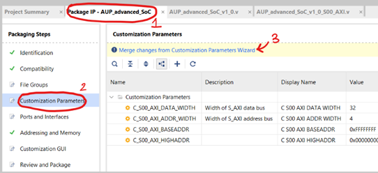
Figure 2.6. Saving all the changes
Click “Review and Package” on the left and select “Re-Package IP” at the bottom of the page. A prompt will appear – select “Yes” to close the project.
Go to the AXI4 peripheral folder you created earlier
\drivers<AUP_advanced_SoC_v1_0>\src and locate a Makefile. In that Makefile, update the contents so that it is the following: COMPILER= ARCHIVER= CP=cp COMPILER_FLAGS= EXTRA_COMPILER_FLAGS= LIB=libxil.a RELEASEDIR=../../../lib INCLUDEDIR=../../../include INCLUDES=-I./. -I${INCLUDEDIR} INCLUDEFILES=*.h LIBSOURCES= $(wildcard *.c) OUTS = *.o OBJECTS = $(addsuffix .o, $(basename $(wildcard *.c))) ASSEMBLY_OBJECTS = $(addsuffix .o, $(basename $(wildcard *.S))) libs: echo "Compiling axi_gpio_asoc..." $(COMPILER) $(COMPILER_FLAGS) $(EXTRA_COMPILER_FLAGS) $(INCLUDES) $(LIBSOURCES) $(ARCHIVER) -r ${RELEASEDIR}/${LIB} ${OBJECTS} ${ASSEMBLY_OBJECTS} make clean include: ${CP} $(INCLUDEFILES) $(INCLUDEDIR) clean: rm -rf ${OBJECTS} ${ASSEMBLY_OBJECTS}Then, click on “Settings” (under “Project Manager”) in the “Flow Navigator” menu on the left. Expand the “IP” section in the new window that appears and choose the “Repository” option.
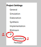
Figure 2.7. Adding IP Repository
Click the “+” option under “IP Repositories” on the right and choose the AXI4 peripheral folder you created earlier (if it hasn’t already appeared) and click “Ok”. Right-click in the empty space of the “Diagram” box again and choose “Add IP”. Type “custom” in the search box and choose “custom_axi_gpio_asoc_v1_0” from the options.
Click “Run Connection Automation” and then click “OK” to connect the AXI-Lite Subordinate interface on GPIO peripheral to the AXI Manager interface on Arm processor.
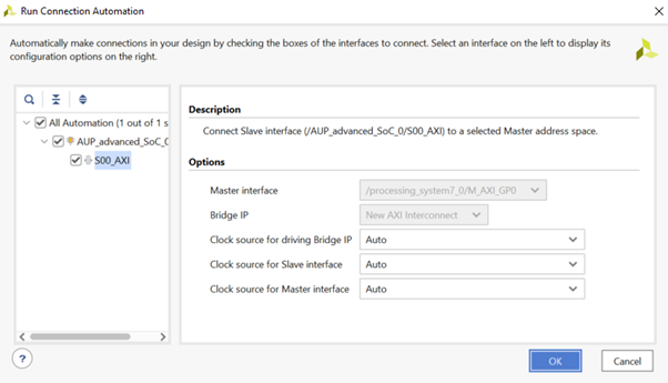
Figure 2.8. Connect AXI-Lite Subordinate interface (Custom IP) to AXI Manager interface
Now that you have created the custom AXI4 peripheral which will control the GPIO, you will connect it up to the ZYNQ Processing System in the next section.