Build a Privacy-First LLM Smart Home on Raspberry Pi 5
Introduction
Run LLMs locally on Raspberry Pi 5 for Edge AI
Set up software dependencies on Raspberry Pi 5 for Ollama and LLMs
Test Raspberry Pi 5 GPIO pins for smart home devices
Build and Run a Smart Home Assistant on Raspberry Pi 5 with LLMs
Next Steps
Build a Privacy-First LLM Smart Home on Raspberry Pi 5
Overview
The next step is to test the GPIO functionality. In this section, you configure an LED light to simulate a smart home device.
Verify GPIO setup on Raspberry Pi 5
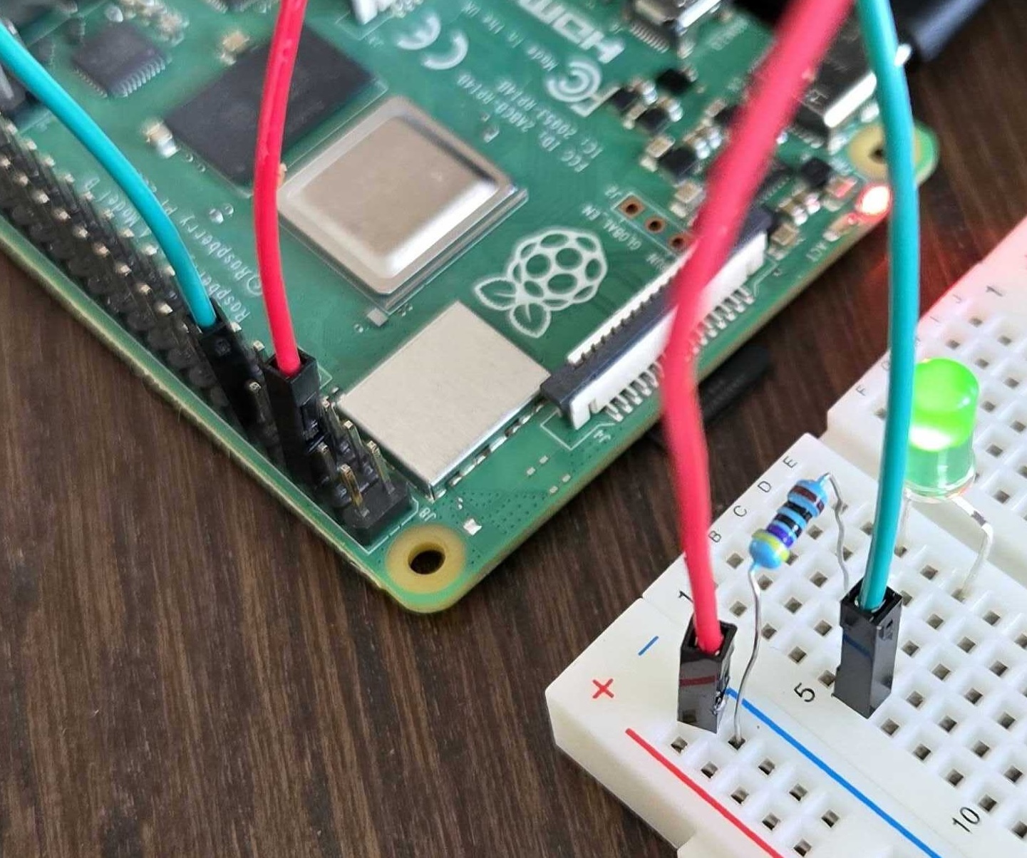
Gather your electronic components. Connect the anode (long leg) of an LED in series with a 220Ω resistor to GPIO 17 (physical pin 11). Connect the cathode (short leg) to a ground (GND) pin.
See the image below for the full setup:
 Raspberry Pi connected to a breadboard with a green LED and jumper wires
Create a Python script named testgpio.py:
cd $HOME/smart-home
vim testgpio.py
Add the following code to the file:
#!/usr/bin/env python3
import time
from gpiozero import Device, LED
from gpiozero.pins.lgpio import LGPIOFactory

# Set lgpio backend for Raspberry Pi 5
Device.pin_factory = LGPIOFactory()

# Set up GPIO pin 17
pin1 = LED(17)

try:
    while True:
        pin1.toggle()  # Switch pin 17 state
        time.sleep(2)  # Wait 2 seconds
except KeyboardInterrupt:  # Ctrl+C pressed
    pin1.close()  # Clean up pin 17
Run the script:
python testgpio.py
The LED should blink every two seconds. If you observe this behavior, your GPIO setup works correctly.
If you run into issues with the hardware setup, check the following:
- Fix missing dependencies with:
sudo apt-get install -f - If you encounter GPIO permission issues, run Python scripts with
sudoor add your user to thegpiogroup. Don’t forget to log out for the changes to take effect:sudo usermod -a -G gpio $USER - Double-check wiring and pin numbers using the Raspberry Pi 5 pinout diagram
- Ensure proper LED and resistor connections
- Verify GPIO enablement in
raspi-configif needed - Use a high-quality power supply
With GPIO pins working, you can now move on to the next section to interact with devices using language models and the user interface.